Revision 1: 25/06/2016
Abstract
This article describes a system that is able to provide a possible conventional explanation (not necessarily the only one) about the “self-sustained” phenomenon observed in the E-Cat steam-generator. During a few tests performed on the above-mentioned E-Cat system an anomalous water steam production was reported and confirmed by a number of observers.
The proposed system also allows explaining:
- How a steam generator is able to produce overheated steam in unusual stable manner
- How in the self-sustained regime (input power switched off) for a short period the quantity of steam produced does not undergo any considerable reduction and a steam temperature increase can even be detected
- How, without further modifications, with a joint production of a small amount of steam and [mostly] water in liquid form at 100°C it is possible to measure an apparent output power to input power ratio (commonly defined as COP) equal to 7
As the article is only a case study, the system dimensions are not considered critical, as dimensions of the real E-Cat changed several times during the years.
Working principle
The working principle of the system is described as follows: the electrical resistance does not heat directly the water mass contained into the generator chamber, but only via a mass of high thermal capacity; the water mass receives the thermal energy through the insulating layer surrounding the thermal mass. Once the system reaches the steady state regime, the insulation layer allows to maintain the thermal mass at high temperature, in the order of 700-1000°C, and the outer surface of the insulating layer at a temperature slightly higher than 100°C.
Description
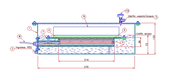
In Figure 1 the drawing section of the steam generator system is shown.
Figure 1 shows the drawing section of the steam generator system. The system dimensions are shown and are not considered critical the goal being only to demonstrate the possibility to have an apparently self-sustaining set-up.
In the figure, the following elements appear:
- External system housing (AISI304)
- water inlet pipe
- steam outlet pipe
- thermal mass (AISI304)
- electrical cartridge heating elements, (n. 4 450W each)
- thermal insulation (kaolin wool)
- thermal mass housing (AISI304)
- input power supply cable
- aluminum fin heat exchanger (PFHE)
- temperature probe
If we consider a system with a square section fully filled chamber contains 14 liters of water, whereas in the case that the chamber is filled just until the level indicated in the drawing it contains about 8 liters of water. The thermal mass of [200]x[200]x[20] mm is about 6.5 kg.
Dimensioning
As an example, in steady state regime, a 1800 W electrical input power of, in absence of anomalous phenomena, produces about 3 kg/h of steam. To provide an indication, in the following link a small video related to a steam jet of 7 kg/h slightly overheated is shown:
When the electrical resistances are switched off for a short period, the heat accumulated into the thermal mass maintains the system in apparent constant thermal power supply; then the mass will cool down (continuing to supply approximately 1800W, without receiving any energy by the electrical resistances).
The evolution of the system temperature T is described by the energy balance of thermal mass:
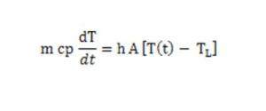 where m is the thermal mass, cp the specific heat, h the heat transfer coefficient and A the exchange surface.
The solution is:
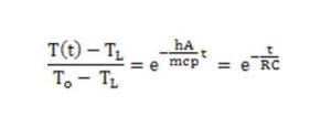 It is easily seen that we can model the cooling phase to a RC circuit, where:
- the heat capacity is equivalent to the capacitor
- the thermal resistance is equivalent to electrical resistance
- the heat is equivalent to the electric charge
- the temperature is equivalent to the voltage
The thermal resistance R can be assumed constant under the following assumptions: constant water level inside the steam generator and heat transfer coefficient weakly dependent on temperature.
Assuming the thermal mass made of 6.5 kg stainless steel , a 900°C initial temperature and the system in equilibrium (steam produced equivalent to a power of 1800W or 1550 kcal/h), the thermal capacity of the mass is estimated to be:
C = 0.12 * 6.5 = 0.78 kcal/°C
where 0.12 kcal/kg °C is the specific heat of stainless steel.
The thermal mass temperature in the cooling phase is described by the following equation:
T(t) = TL + ΔT0 * e-(t/RC)
where R is the thermal resistance, between the mass and boiling water, and C the thermal capacity (0.78 kcal/°C = 3260 J/°C); TL is the asymptotic temperature (when time goes to infinity), in this case 100°C.
The thermal resistance is equal to:
R = (900-100)/1550 = 0.51 h°C/kcal
During the self-sustained phase, the thermal mass temperature evolution vs. time is:
T(t) = 100 + 800 * e-[t / (0.51 x 0.78)]
and after 30 minutes (0.5 hours) the temperature is:
T(t) = 100 + 800 * e -(0.5 / 0.40) = 330°C
The quantity of steam produced after 30 minutes is:
Q = Q(0) * (330 – 100) / (900-100) = 0.28 * Q(0)
This simply means that, after 30 minutes, the system is still producing overheated steam, altough with a throughput reduced to about a quarter of the initial one, a quantity, however, not negligible.
Based on the previously calculated thermal resistance, assuming negligible the thermal resistance between the outer surface of the housing and the water mass, the thickness of the insulation required between the mass and the housing can be approximately estimated.
Assuming the housing surface of 0.12 m2 and the insulation made of pressed kaolin-wool (with an average thermal conductivity λ = 0.1 W/m°C in the temperature range 100 to 900 °C ), the thickness turns out to be:
s = λ * S * ΔT / P = 0.1 * 0.12 * 800 / 1800 = 0.0053m = 5.3mm
where s = thickness; P = power; λ = thermal conductivity; S = surface and ΔT = temperature difference.
Temperature of the housing box
The thermal mass is at a high temperature, while the housing box (indicated by 7 in Figure 1) is at a much lower temperature thanks to the thermal insulation layer (indicated with 6 in Figure 1) and the high heat transfer coefficient with the surrounding water.
It is worth to distinguish between the housing parts in contact with water and the housing top cover in thermal contact with the aluminum plate-fin heat exchanger (PFHE).
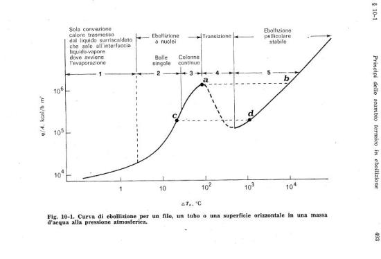
Assuming that the water level is just at the base of the PFHE, considering the following diagram (extracted from F. Kreith – Principles of heat transfer), the temperature of the housing surface in contact with water can be estimated, without performing complex calculations on convective heat transfer.
The bottom and laterals surfaces of the housing box are about 2/3 of the overall surface. Since the cross heat transfer of the walls is negligible, it can be assumed that 2/3 of the thermal power (1200 W) is transferred to water by a surface of 0.08 m2. The heat flux through that surface is 15,000 W/m2 or 13,000 kcal/hm2; considering the diagram previously shown it is possible to deduce that the boiling phenomenon is in pure convective zone or at most in the top of nuclei boiling zone. Nevertheless, the temperature difference between the water mass (100°C) and the housing surfaces is extremely low, definitely less than 5°C.
As before mentioned, the case of the top housing box in contact with aluminum PFHE is different. Assuming that the PFHE exchanges heat only with steam (water level just below the PFHE) the remaining power of 600W is transferred only to the steam mass. Considering a steam production of about 2 kg/h, even assuming the exchange surface extremely high, the temperature of PFHE and overheated steam is:
T = 100 + 600 * 0.86 / (2 x 0.46) = 660 °C
being the specific heat of steam about 0.46 kcal/kg°C in the operating conditions.
In order to maintain the temperature of the PFHE below a critical level, it is necessary that part of the heat be exchanged with water as well. Therefore, the PFTE must be partially covered with water. In this way, the PFTE temperature can be controlled in the range of 110-115°C, with the aim to produce overheated steam. It is worth to notice that by a common thermal-controller it would be possible to set simultaneously the output temperature of overheated steam and water level into chamber, as it will be further explained in details in the next paragraphs.
Output temperature of steam
The output steam temperature is a point that caused many debates inside the community. A number of observers, present during the test, claimed that the steam temperature was higher than 100°C and stated that the temperature measurement was performed at atmospheric pressure; according to the above, the conclusion is that the system produced overheated steam. Part of the technical community challenged this statement, because an overheated steam generator would be extremely unstable: a small variation in water flow rate or in the input power (or hypothetically in an internal exothermic reaction) would affect strongly the output steam temperature; although the observers stated that the system was very stable.
The system proposed in this document enables to produce overheated steam in a very stable manner, this is thanks to the presence of a plate-fin heat exchanger (PFHE), indicated by 9 in Figure 1, located on the top of the heating chamber and only partially covered from water. The PFHE model used is assumed to be Elbomec S-220 type. The steam, released from the water interface, is overheated passing through the PFHE; the steam temperature depends on the steam mass flow rate and the PFHE area . Considering the large area of the PFHE surface and the reduced quantity of produced steam, the PFHE temperatures and the output steam are very close each other.
In self-sustaining regime, the resistances are switched off, while maintaining the water pump running, and a slow decreasing of steam temperature is expected. Actually, in case a thermostat controls the water level, the steam temperature will stay constant for long period, as shown in the “Dimensioning” part: what will decrease with time is only the steam production. It is worth to notice that increasing the set point in the thermostat (manual or automatic) could even simulate an increase of the output steam temperature.
Water level control
The water level into chamber is fundamental for to get a proper simulation of a “self-sustaining” phase. A too low water level could overheat the aluminum plate-fin heat exchanger (PFEH). Conversely, a too high water level can cooling the PFEH too much, thus reducing the steam output temperature that, in this case, would be no longer overheated.
As already mentioned, the water level may be controlled by a level sensor, anyway a start/stop feedback controller on a fix temperature set-point of the outlet steam (typically 110 ° C) appears to be a simple and perfectly working control method. In this case, in order to avoid dangerous overheating during the heating start-up phase, it is necessary to fill the chamber until the water reaches the thermal mass housing bottom.
To prove that the proposed regulation method is easy to implement and able to maintain stable water level and temperature, the reaction time of such control system is estimated below.
Assuming that the water level drops below the aluminum plate-fin heat exchanger, temperature starts to increase as a result of the input thermal power of about 600W received from the insulating material that separates the thermal mass. In this condition, the PFHE transfer a very small heat to the surrounding steam (assuming the output steam temperature of 110°C the estimated thermal exchanged power is approximately 30W). The mass of the PFHE is about 3kg, the specific heat of aluminum is of 0.24 kcal/kg°C; the temperature-increasing rate of the aluminum PFHE is approximately:
ΔT / t = 600 * 0.86 / 3 * 0.24 = 716 °C/h = 0.2 °C/s
This means that, a control system having a reaction time less than 5 seconds would cause temperature fluctuations of 1°C. A normal ON/OFF controller on the pump, with feedback signal from the output steam temperature (110 °C), can be easily used.
Steady state time
The time to achieve a steady state is certainly increased by the thermal mass. However, contrarily to what can be assumed, most likely not all the water inside the generator is at 100°C; as a consequence, the energy transferred to the thermal mass is partially compensated by the fact that only a part of the water is heated.
The heater is located in the upper part of the steam generator, contrary to what happens in a common boiler, which is heated from the bottom. In a boiler, the water shows an almost uniform temperature due to the internal convective flow; while, in the described system, convective flows are practically absent and the only stirring effect is caused by the small steam bubbles developed on the external parts of the thermal mass housing. From the Figure 2 one can be deduce that boiling is practically absent in the liquid bulk and mainly located in the surface contacting the housing; it is plausible to conclude that the water at the bottom of the generator chamber remains at a temperature not much higher than the input one.
The steady states time can be estimated considering the total energy required to get the thermal mass at 900°C and to bring to 100°C a portion of water, assumed to be of 4 liters.
The description of a system in a dynamic regime requires rigorous calculations and it is very complex, so only a rough estimation is showed below:
- Energy supplied to thermal mass = 6.5 * 900 * 0.12 = 700 kcal
- Energy supplied to water = 4 * 80 = 320 kcal
- Total energy supplied = 700 + 320 = 1020 kcal
- Time to provide such energy = 1020/ (1800 * 0.86) = 0.65 h = 40 minutes
Considering that in the meanwhile, the energy is being transferred to the developed steam, it is possible to conclude that the system achieve approximately the steady state regime after about 1 hour (it is necessary to clarify that in theory the steady state is achieved at infinite time). The steam production instead will start well before, as soon as the external housing surface exceed 100°C.
System stability
Contrary to what might be expected, a stable production of overheated steam could therefore be possible, even considering fluctuations of either input power or water flow rate.
For example, a sudden 10% decrease of power, from 1800W to 1600W, is analyzed (similar approach can be applied to increasing power). The temperature-decreasing rate of the thermal mass is:
dT/dt = ΔP / C = (1800 – 1600) / 3260 = 0.06 °C/s = 3.6 °C/minute
Therefore, to reduce by 50°C the thermal mass temperature, a 15 minutes are required; such a temperature drop is negligible compared to the initial 900°C temperature and would cause an output steam temperature variation of less than 1°C.
Now a pump breakdown is analyzed. In this case, as previously shown the temperature of the aluminum plate-fin heat exchanger increases with a rate of 0.2°C/s and could achieve a critical temperature of 300°C after 15 minutes. However, the temperature of the thermal mass would decrease as well, and considering that, in this condition, the heat exchange with the steam (which would be highly overheated) would be very important, it can be said that the system would cool down without any part reaching temperatures able to cause damages.
In conclusion, the system can be controlled easily and by hands, without any fast feedback loop.
Simulation of COP = 7
The described system is able to simulate an output thermal power 7 times higher than the input power (COP = 7).
Assuming a system in steady state regime and the 25°C temperature for inlet water is, the about 3 kg/h of slightly overheated steam can be produced. Let us now assume to increase 6 times the water flow rate , up to 18 l/h.
The heat required to bring the water at boiling temperature (100 °C) is:
Q = 18 * (100 – 25) = 1350 kcal/h = 1570W
Since the supplied input power is 1800 W, it is sufficient to bring the water at boiling and further to produce a small amount of steam (in absence of thermal dissipation the steam production is estimated to be 0.4 kg/h).
The main point is that most of the inlet water is not vaporized, but flows out from the output pipe (3 in Figure 1) at a temperature of 100°C.
In these conditions, a temperature probe introduced in the upper part of the steam generator chamber would measure a value of 100°C or slightly higher, giving the wrong impression that the system is producing steam in large quantities while in reality only water at 100°C is flowing out.
According to what has been said above, the output thermal power can be [wrongly] estimated based on the following (1800W input power):
Q = 18 * (75 + 545) = 11160 kcal/h = 12970 W
Apparently a value equal to a COP = 7.
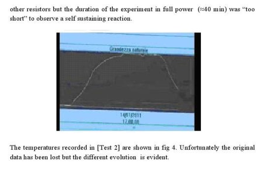
As already mentioned, in the described system, temperature and level controls are not required, being sufficient to provide a constant input pump flow rate of about 18 l/h. A small reduction of the flow rate would not have any relevant effect as the system would continue to work properly, only showing a slightly reduced apparent COP, since more steam is produced. On the contrary, increasing the water flow rate, more than 5%, could cool the water below 100°C, a decreasing that for example was observed in the following Report that refers to a test executed in Jan ’11 (screen shot of collected data), as shown in Figure 3.
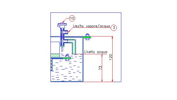
It is worth to notice how it would be enough to extend the outlet pipe in the steam generator chamber roughly until the water level, as shown in fig 4, to obtain an apparent steam production with a COP = 7 and simultaneously to measure a much higher temperature than 100°C into the chamber.
In this configuration during the self-sustained phase the aluminum plate-fin heat exchanger would remain partially not covered from water, as consequence it could achieve a temperature higher than 100°C allowing to overheat the small quantity of steam produced.
Heating resistors
The only critical commercial component of the system is the heating resistance; in fact, this element has to work at very high temperatures and therefore with a high risk of failure due to local overheating.
In Figure 1 cartridge heater elements appropriate for this application are shown. The most common electrical resistances available in the market are able to operate with a surface temperature up to 750°C and a surface power density of 50W/cm2, but specific models can operate continuously over 1000°C (e.g. cartridge heaters made of boron nitride from TRE C co. Segrate (MI); 12.5, 14 and 16 mm standard diameters are available).
In the drawing n. 4 resistors, each 450 W of power, 12.5mm diameter and 200 mm long are indicated. The surface power density is less than 6 W/cm2, which is almost 10 times less than the maximum allowable. This over-sizing allows operating with isolated resistors (made in boron nitride) at extremely high surface temperatures, even considerably higher than 1000°C and guarantees that in each point of the stainless steel block the temperature is almost identical to the surface of the heater elements. In fact, considering the dimensions shown in Figure 1 and that the thermal conductivity of stainless steel is about 17 W/m°C, the maximum temperature difference estimated in the block of stainless steel is in the order of +/- 30°C, thus negligible compared to the 900°C operating temperature.
Conclusion
The system described in this article could explain an apparent over-unity COP or the ability to continue to supply overheated steam at the output even though the input power supply is switched off (self-sustaining mode), without requiring anomalous internal exothermic reactions.

